Avoid ES-1 Roof Edge Failures: 8–10 ft Mock Ups for Contractors
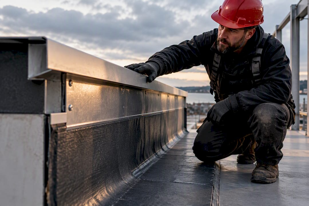
Practical ES-1 roof edge checklist for contractors: require RE-1/RE-2/RE-3 test reports, 8–10 ft mock ups, exact cleat geometry, and tested as installed...
ANSI/SPRI/FM 4435/ES-1 is the U.S. test standard for wind resistance of low-slope roof edge metal, and the International Building Code leans on it directly for built-up, modified bitumen, and single-ply systems. The immediate action for contractors and specifiers: source edge metal that carries an ES-1 test report matching your project’s geometry, or document shop fabrication with equivalent testing, then install it exactly as tested. No field improvising on cleat depth, fastener spacing, or termination detail.
TL;DR:
- Contractors must ensure that installed metal edge systems exactly match the tested assembly geometry specified in ES-1 reports, as field modifications can invalidate compliance.
- ES-1 covers low-slope roof edges with three tests (RE-1, RE-2, RE-3) that measure membrane grip, fascia capacity, and coping uplift, and must match the project’s calculated wind pressure from ASCE 7.
- Proper attachment of cleats, fastener spacing, and nailer strength are critical, with field deviations such as wider fastener spacing often leading to failures despite passing the lab test.
- Specification documentation should include exact test method, geometry, and allowable pressure, with factory or shop-fabricated systems preferred over on-site modifications.
- Regular inspections post-installation in spring, fall, and after high-wind events can catch issues early, as most failures stem from installation errors rather than material defects.
Table of Contents
- What Does ES-1 Cover, and Why Does It Exist?
- What Do RE-1, RE-2, and RE-3 Actually Measure?
- How Do IBC and ASCE 7 Determine Your Design Pressure?
- Why Do Edge Details Fail in the Field When the Test Passed in the Lab?
- How Do You Specify or Source ES-1-Compliant Edge Metal?
- Contractor Checklist: Plan, Install, Inspect
- How Has the ES-1 Standard Changed Since It Launched?
- How Does ES-1 Compare to Other Edge Standards?
- What Do Successful and Failed ES-1 Installations Actually Look Like?
- How Often Should ES-1 Roof Edges Be Inspected After Installation?
- What Specification Pitfalls Show Up Most on Real Jobs?
- How MidAtlantic Metal Systems Supports ES-1-Compliant Edge Work
- Key Standards and Programs Worth Consulting
- Sources
- FAQ
What Does ES-1 Cover, and Why Does It Exist?
ES-1 governs edge metal on low-slope roofs, meaning slopes at or below roughly 2:12, on built-up, modified bitumen, and single-ply membrane systems. Gutters fall under a separate companion standard, GT-1, and certain assemblies (many through-fastened metal panel systems and spray polyurethane foam roofs) sit outside ES-1’s test applicability entirely, according to IIBEC. Confirm your roof type before assuming the standard applies.
SPRI developed ES-1 in the late 1990s, and FM Global joined the standard in 2011, folding its own wind-uplift expertise into the test protocol. That collaboration is why you’ll see it written as ANSI/SPRI/FM 4435/ES-1 in specs and code references rather than just “ES-1.”
The stakes are real. Roof perimeters and corners see the highest wind pressures on any low-slope roof, and a failed edge doesn’t just lose a strip of metal. It peels back membrane, opens the field to wind-driven water, and turns a $2,000 repair into a full reroof claim. Insurers know this, which is one reason ES-1 compliance shows up in underwriting conversations as often as in permit reviews.
What Do RE-1, RE-2, and RE-3 Actually Measure?
ES-1 isn’t one test, it’s three, and each one targets a different failure point on the edge assembly.
RE-1 evaluates the membrane termination, essentially how hard you can pull on the membrane edge before the anchoring detail lets go. This is the test most relevant to the roofing membrane’s grip on the edge system itself.
RE-2 applies outward pull on the vertical fascia face, simulating the suction wind generates as it wraps around a building corner. The resulting numbers tell a designer how much fastener and cleat capacity the fascia detail actually delivers, which then gets compared against the calculated design pressure for that zone.
RE-3 is the coping test, and it’s bidirectional: up-and-out forces on a two-piece coping cap, mimicking the way wind lifts and pulls simultaneously at a parapet edge. Coping details fail differently than fascia details, so this test exists as its own category rather than a variant of RE-2.
The detail that trips up more crews than any other: ANSI/SPRI/FM 4435/ES-1 certifies a specific tested assembly, not a general product category. Change the cleat leg length, the fastener spacing, or the attachment method in the field, and you’re no longer installing what was tested. The lab report is only valid for the geometry it describes.
How Do IBC and ASCE 7 Determine Your Design Pressure?
The code doesn’t just suggest ES-1 testing, it requires it. Building departments enforcing the IBC reference edge metal test methods for low-slope membrane roofs, tying that requirement back to the wind load provisions in Chapter 16, which point to ASCE 7 for the actual numbers.
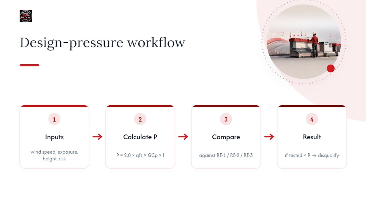
Here’s where a lot of specifiers get tripped up: ES-1 testing tells you what an edge assembly can resist. It does not tell you what your project needs it to resist. That second number comes from ASCE 7, using basic wind speed for the site, exposure category, mean roof height, and the building’s risk category (which sets the importance factor).
Those inputs feed a design equation, expressed roughly as P = 2.0 × qfz × GCp × I, where qfz is the velocity pressure at the relevant height, GCp is the pressure coefficient for that roof zone, and I is the importance factor. The 2.0 multiplier is a built-in safety factor specific to edge metal design. Once you have that pressure number, you compare it directly against the tested resistance in the RE-1, RE-2, or RE-3 report. If the tested value doesn’t clear your calculated design pressure, that edge metal doesn’t qualify for the project, full stop.
One more thing worth double-checking every single time: the specific edition of IBC and ASCE 7 your local authority having jurisdiction has adopted. Jurisdictions lag behind the latest editions by years in some cases, and wind speed maps change between editions.
Why Do Edge Details Fail in the Field When the Test Passed in the Lab?
Most ES-1 failures aren’t standard failures. They’re installation failures wearing a standard’s name.
Cleat engagement is the single biggest variable. Field testing and Wall of Wind research have shown that small misplacements in cleat seating can drop an edge assembly’s real-world capacity well below its tested rating, sometimes catastrophically so, according to Professional Roofing. L-shaped cleats with longer engagement legs are more forgiving of minor field variance than short straight cleats, which is why that geometry keeps showing up in updated ES-1 test assemblies.
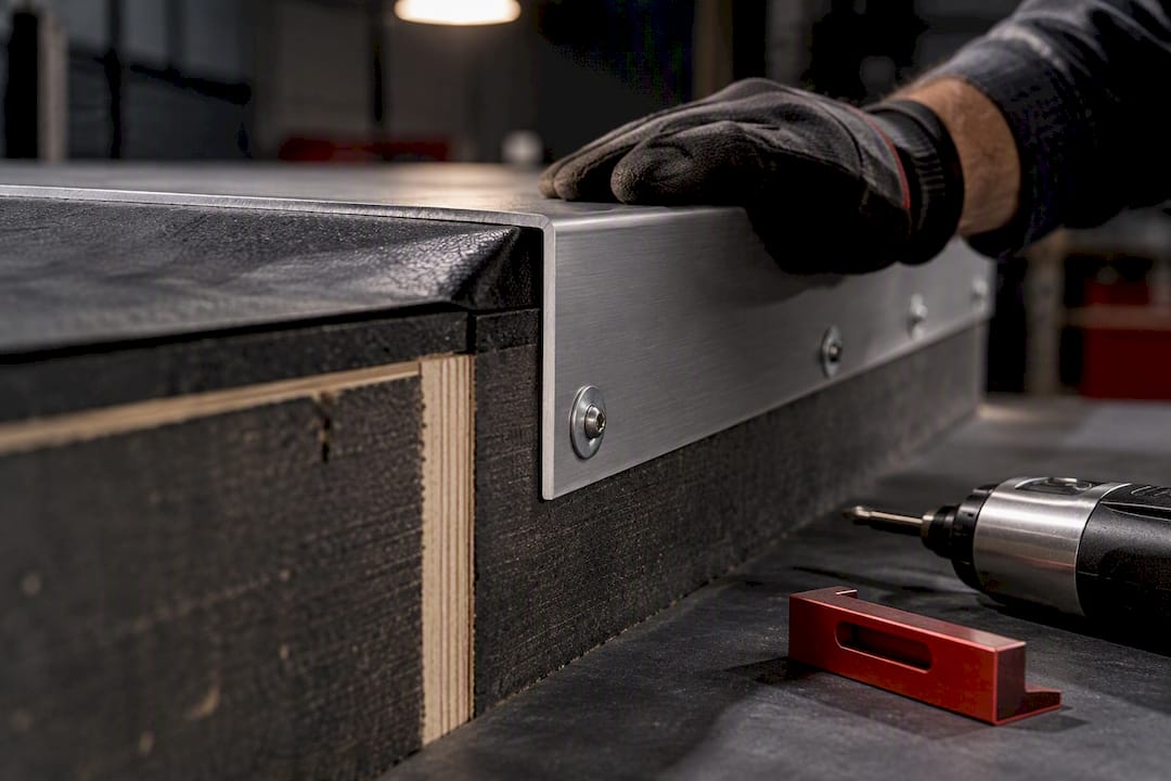
Nailer strength matters just as much, even though ES-1 doesn’t test it. The standard measures the edge assembly’s resistance, not the wood blocking’s ability to transfer that load into the structural deck. A perfectly tested cleat fastened into a rotted or undersized nailer is still a failure waiting to happen.
A few other field details that decide whether a tested assembly performs as tested:
- Fastener gauge and spacing must match the tested schedule exactly, not “close enough.”
- Cleat material gauge needs to correspond to the fascia gauge specified in the test report.
- Slip sheets are required at metal panel edges to accommodate thermal movement without tearing loose the termination.
- Drip edge sequencing at eaves and rakes should follow documented overlap and fastening guidance for high-wind zones.
Pro Tip: Before the crew starts the perimeter, pull a sample cleat and fascia piece and physically check engagement depth against the test report’s drawing. Five minutes with a tape measure catches the mismatch that a wind event will find for you later.
How Do You Specify or Source ES-1-Compliant Edge Metal?
Premanufactured, factory-tested edge systems are the lower-risk path when the project’s wind pressures are high or the building shape creates unusual corner and parapet conditions. You get a lab report tied to a specific, repeatable product, and the fabricator has already done the engineering.
Shop-fabricated edge metal is acceptable too, but it needs its own documentation trail. NRCA maintains a testing and sub-listing program specifically for this, letting fabricators demonstrate that their shop-built profiles meet ES-1 resistance values without paying for a full independent test on every job.
What to actually require in submittals:
- The specific test method (RE-1, RE-2, or RE-3) that applies to each edge condition on the project.
- The exact specimen geometry from the lab report, including cleat leg length, fastener type, and spacing.
- The allowable design pressure the tested assembly achieved, stated in the same units used in your ASCE 7 calculation.
- A copy of the lab report itself, ideally from FM, UL, or Intertek, or NRCA’s sub-listing documentation.
- Mock-up requirements: a minimum tested length (commonly 8 to 10 feet) with the exact fastener pattern specified.
Add “tested-as-installed” language to your specs directly. It’s a short sentence that saves arguments during inspection: the installed assembly shall match the tested specimen’s geometry, fastener type, and spacing without deviation.
Contractor Checklist: Plan, Install, Inspect
Compliance breaks down when it’s treated as a paperwork exercise instead of a sequence of decisions made in the right order.
Pre-bid:
- Confirm which IBC and ASCE 7 editions the local jurisdiction has adopted before pricing the job.
- Require ES-1 test reports as part of the submittal package, not an afterthought after material orders.
Pre-install:
- Verify the tested geometry matches your actual parapet height, fascia depth, and corner conditions.
- Order cleats and edge metal in the exact gauge called out in the test report, and schedule a mock-up section.
During install:
- Follow the tested fastener spacing without shortcuts, even on long straight runs where it feels excessive.
- Confirm nailer attachment to the deck before the metal goes on, since this load path isn’t part of the ES-1 test itself.
- Install slip sheets at panel edges and thermal breaks where the assembly calls for them.
Inspection and closeout:
- Photograph fastener schedules and cleat engagement at representative locations before the membrane covers them.
- File the ES-1 test reports and mock-up photos with the closeout package for future insurance or warranty reference.
How Has the ES-1 Standard Changed Since It Launched?
SPRI introduced ES-1 in the late 1990s to close a real gap: at the time, there was no standardized way to test whether edge metal could survive the wind loads that field data showed were concentrating at roof perimeters. Early adoption was scattered, driven mostly by insurers pushing for better documentation on claims-prone assemblies.
The turning point came in 2011, when FM Global merged its own edge-testing protocol into the SPRI standard, creating the combined ANSI/SPRI/FM 4435/ES-1 designation still used today. That merger mattered because it consolidated two testing philosophies (SPRI’s membrane and code focus, FM’s insurance-loss focus) into one document that code bodies could reference cleanly.
IBC adoption followed in stages rather than all at once, with different code cycles picking up ES-1 language at different paces across jurisdictions. By the 2021 and 2024 IBC cycles, NRCA confirms that both ES-1 and its companion gutter standard, GT-1, are directly referenced for low-slope edge metal and gutter systems respectively.
More recent updates have focused on refining test specimen geometry, particularly around cleat design. The shift toward recommending L-shaped cleats with longer engagement legs, rather than older straight-leg designs, came directly out of lab and field data showing straight cleats were more sensitive to minor installation variance. SPRI’s companion ED-1 document has also expanded over time to cover design-side guidance, like material thickness and thermal movement allowances, that ES-1’s pass/fail testing doesn’t address on its own.
How Does ES-1 Compare to Other Edge Standards?
ES-1 occupies a fairly specific lane: it’s a pass/fail resistance test for edge metal assemblies on low-slope membrane roofs, not a comprehensive design code. That distinction matters when you’re comparing it to adjacent standards.
GT-1, its sibling standard, covers gutters specifically, using similar pull and load test logic but different specimen configurations since gutters carry water load and different structural attachment patterns than a fascia or coping edge.
ASCE 7 itself isn’t a competing standard so much as the source of the design-side numbers ES-1 test results get compared against. Where ES-1 answers “what can this specific assembly resist,” ASCE 7 answers “what does this specific building need it to resist.” Neither one works without the other in a compliant design.
Outside the roofing edge world, other wind-resistance test regimes exist for different building envelope components, window and door assemblies use their own ASTM impact and pressure protocols, for instance, but they’re not interchangeable with ES-1 because the failure modes and load paths differ completely. A curtain wall test tells you nothing useful about coping cap uplift.
Internationally, other countries have developed their own wind-uplift test regimes for roof accessories, often influenced by similar insurance-loss data that originally pushed SPRI and FM toward ES-1. None of them substitute for ES-1 on a U.S. project subject to IBC enforcement, though. If your project sits in a jurisdiction enforcing the IBC, ES-1 (or documented equivalent shop testing through NRCA’s program) is the applicable path, regardless of what a manufacturer’s international test data might show.
What Do Successful and Failed ES-1 Installations Actually Look Like?
The pattern in field failure investigations is consistent enough to be almost predictable: the edge metal itself was rated for the wind zone, but the installation deviated from the tested geometry in some small, seemingly harmless way.
A common failure scenario involves a properly specified cleat system where the installing crew, working fast on a long parapet run, spaced fasteners a few inches wider than the tested schedule to save time and material. The assembly held through several wind events, then failed during a stronger storm precisely because the wider spacing had quietly reduced the load capacity below what the corner and perimeter zones actually experienced. Wall of Wind testing has replicated this exact failure mode under controlled conditions, confirming that fastener spacing deviations, not material defects, are usually the culprit.
Successful installations tend to share a boring but effective trait: the mock-up section actually got inspected and approved before the rest of the perimeter went up, and the crew treated the tested fastener schedule as a fixed requirement rather than a starting point for field adjustment. Projects with tested-as-installed language built into the specification also tend to generate fewer post-storm disputes, since there’s a documented baseline to compare against during a claims investigation.
The takeaway that shows up across both good and bad outcomes: the material rarely fails on its own. The gap between the tested assembly and the installed assembly is where almost every documented edge failure originates.
How Often Should ES-1 Roof Edges Be Inspected After Installation?
Roof edges take more abuse over time than the rest of the membrane field, so they need their own inspection rhythm rather than getting folded into a general roof walk.
A reasonable baseline is a visual inspection twice a year, once in spring and once in fall, plus a targeted check after any wind event strong enough to generate a local weather advisory. Look specifically at cleat seams for separation, fastener heads for backing out or corrosion, and coping joints for gaps that weren’t there at installation. Sealant at coping end caps and expansion joints degrades faster than the metal itself in most climates, and a failed sealant joint is often the first visible sign that water is getting behind an otherwise sound edge assembly.
Thermal cycling matters more at edges than in the field of the roof, since edge metal expands and contracts against fixed cleats every day, not just seasonally. Slip sheets and properly sized expansion joints reduce fatigue, but they don’t eliminate it, so a five-year mark is a reasonable point to schedule a closer inspection of fastener tightness and cleat engagement rather than relying on visual checks alone.
Documentation from the original installation earns its keep here. If the closeout package includes photos of fastener spacing and the original test report, a facilities manager or roofing contractor doing a later inspection has something concrete to compare current conditions against, rather than guessing whether an observed gap is new damage or original tolerance. Periodic cleaning also protects finishes and coatings at the edge, and warranty-safe soft-washing guidance is worth following closely since aggressive pressure washing can loosen sealant joints at coping and fascia terminations faster than weather alone.
What Specification Pitfalls Show Up Most on Real Jobs?
Working with contractors across Virginia, Maryland, Washington DC, Pennsylvania, and West Virginia, the recurring problem isn’t a lack of ES-1 awareness. It’s mismatched geometry: a spec calls for one tested assembly, and the ordered material shows up in a slightly different gauge or cleat profile.
Factory-tested edge systems make sense on complex parapets or high-wind zone projects where the engineering margin is thin. Shop-fabricated work with proper testing and NRCA sub-listing documentation works fine on more standard runs, provided someone actually checks that the fabricated profile matches the sub-listing’s tested geometry. Either path is legitimate. What’s not legitimate is skipping the paperwork on either one. Require tested-as-installed proof in every submittal package before material gets ordered, not after it’s already on the roof.
— Matt Catino
How MidAtlantic Metal Systems Supports ES-1-Compliant Edge Work
Matching tested geometry gets a lot easier when the panels, trim, and edge metal actually arrive at the job site cut to the lengths your spec requires. MidAtlantic Metal Systems supplies custom-length standing seam panels built from 24-gauge and 26-gauge Englert steel, along with coordinated trim and flashing packages sized to match the cleat and fascia dimensions called out in your ES-1 test report, not a generic stock profile that forces field modification.
That precision matters most on the projects where field cutting introduces the most risk: tight parapets, complex corner conditions, and long runs where fastener spacing has to stay exact for hundreds of feet. Cut-and-drop delivery cuts down the on-site trimming that so often leads to the small geometry deviations that undercut tested capacity, and on-site standing seam roll forming gives crews a way to produce exact panel lengths for oversized or unusually shaped roofs without warehousing excess stock.
If you’re bidding a project with strict ES-1 requirements, request matching test documentation for your trim and edge metal order, plan for mock-up pieces before the full run ships, and reach out to the team for job-specific guidance on gauge and profile selection.
Key Standards and Programs Worth Consulting
Keep ANSI/SPRI/FM 4435/ES-1 itself on hand for the RE-1, RE-2, and RE-3 test method language, and pair it with SPRI’s ES-1 quick reference guide for code linkage. Confirm your project’s ASCE 7 wind inputs against the IBC edition your jurisdiction has adopted, and lean on NRCA’s shop-fabricated edge metal testing program whenever a fabricator’s sub-listing documentation needs verification against a submitted lab report.
Sources
- Testing of Shop-fabricated Edge Metal (NRCA)
- Living on the edge — Professional Roofing (2024)
- Roof edge protection guidance (BASC/PNNL / IBHS resources)
FAQ
What is ES-1 compliance and why is it required?
ES-1 compliance means the edge metal on a low-slope roof has been tested under one or more of the RE-1, RE-2, or RE-3 methods and shown to resist the wind pressure your project’s ASCE 7 calculation requires. The IBC requires it for built-up, modified bitumen, and single-ply roofs because edge details concentrate the highest wind loads on a roof, making them the most common failure point in wind events.
What is the 25 rule in roofing?
There’s no formally recognized “25 rule” tied to the ES-1 standard or IBC edge metal requirements. If you’ve heard this term applied to a specific reroofing or recover threshold, it likely refers to a separate local code provision rather than anything in ANSI/SPRI/FM 4435/ES-1, and it’s worth confirming directly with your local building department.
What is the code for drip edge?
Drip edge installation at eaves and rakes typically follows fastening and overlap guidance detailed in BASC/PNNL roof edge protection resources, which recommend fully adhered underlayment at these locations in high-wind zones along with specific overlap and fastener spacing. The exact code section depends on which IBC edition your jurisdiction has adopted, so confirm locally before finalizing a spec.
What are the details of ES-1 coping?
ES-1 coping performance is measured through the RE-3 test, which applies bidirectional force (both upward and outward) to a two-piece coping cap assembly to simulate real parapet wind conditions. Cleat engagement depth and L-shaped cleat geometry make the biggest difference in whether a coping detail performs at its tested rating once installed, according to Wall of Wind research.
Does MidAtlantic Metal Systems supply edge metal matched to ES-1 test geometry?
MidAtlantic Metal Systems fabricates custom trim and flashing and cut-and-drop standing seam panels sized to a project’s specified dimensions, which helps contractors avoid the field trimming that often causes geometry mismatches against a tested assembly. Contact the team directly with your test report specifications for gauge and profile guidance on a specific project.