12–60 in. Purlin Spacing: Contractor Checklist for Standing Seam Roofs
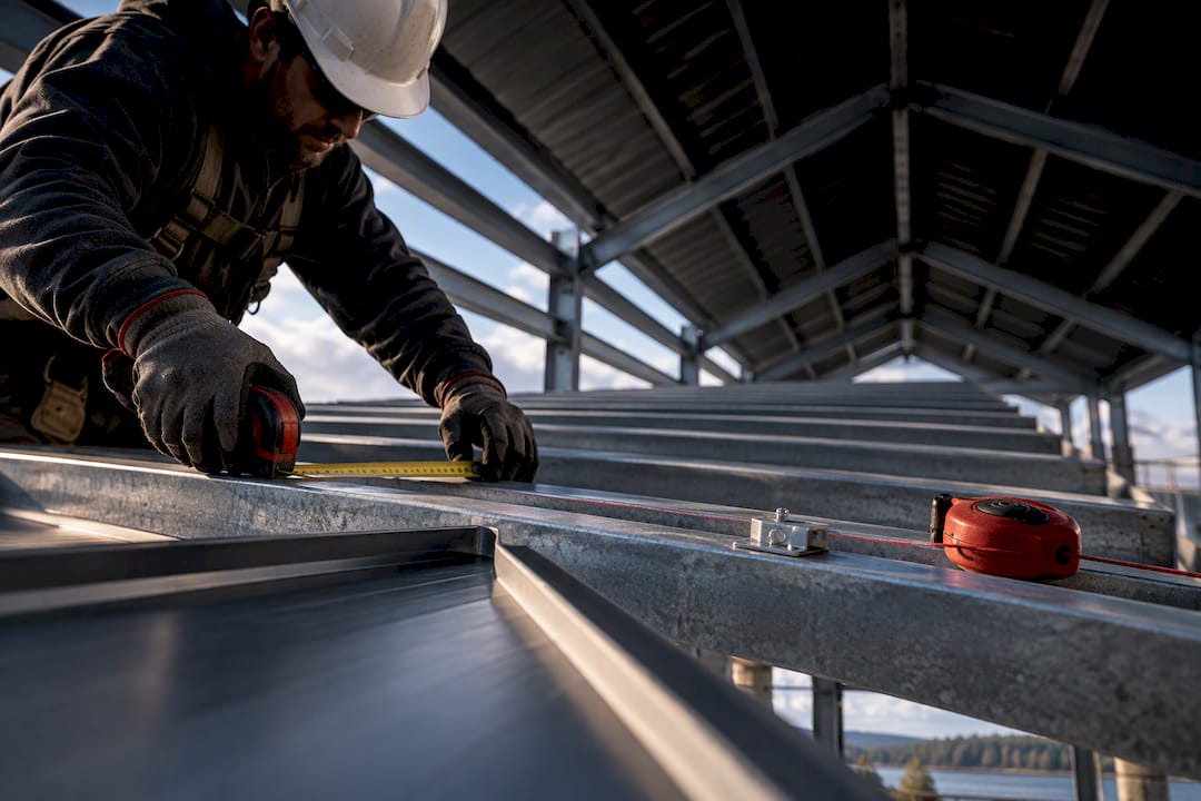
Contractors: confirm purlin spacing on standing seam roofs with a practical on-site checklist, manufacturer load/span lookup, 12–60 in. examples, and...
Realistic purlin spacing for standing seam roofing typically runs within a practical range on center, but the number that matters is the one printed on the manufacturer’s load and span table for your specific panel, clip, and load combination. A worked structural design example uses 5 feet of purlin spacing with 24 inch clip spacing, proving wide spans are possible when the engineering supports them. Skip the table or the engineer’s sign off, and you are guessing.
TL;DR:
- Purlin spacing must be verified against manufacturer load and span tables that account for specific panel gauge, clip type, and load conditions; general ranges are 12-24 inches, 24-36 inches, and up to 60 inches in engineered cases.
- The allowable spacing is influenced by factors such as wind uplift, snow loads, panel stiffness, clip type, purlin section capacity, and deflection limits, which interact complexly and require careful consideration.
- Proper clip selection and placement significantly alter in-plane stiffness, with fixed clips providing more restraint at tighter spacing and sliding clips allowing thermal movement but shifting load to the panel and purlin.
- Precise purlin alignment and straightness are crucial to avoid seam mis-engagement, oil-canning, or visible waviness, with industry-recommended tolerances around L/500 for straightness.
- For project-specific spacing beyond 36 inches or in high-wind zones, consulting a structural engineer and verifying with manufacturer tables is essential to ensure performance and code compliance.
Table of Contents
- Typical purlin spacing ranges and field examples
- Primary factors that control allowable purlin spacing
- How clip spacing and panel geometry interact with purlin spacing
- Installation tolerances and alignment: preventing oil-canning and seam problems
- Design verification: using manufacturer load/span tables and when to call an engineer
- Contractor’s on-site checklist for confirming purlin spacing before panel delivery
- Practical resources and recommended contractor references
- Field perspective: common mistakes and quick mitigations
- How MidAtlantic Metal Systems can support correct purlin spacing and installation
- Sources
- FAQ
Typical purlin spacing ranges and field examples
Contractors rarely deal with one spacing number. They deal with a band that shifts based on panel gauge, clip type, and the loads a roof has to survive. Documented ranges give a useful starting frame, but they are not a substitute for a project-specific table.
- 12 inches to 24 inches on center shows up on shorter spans with tighter clip spacing, often where wind uplift pressures are high or the panel profile is thinner.
- 24 inches to 36 inches on center covers a large share of standard commercial and residential jobs where panel gauge and clip spacing fall in a middle range.
- 48 inches to 60 inches on center appears only in engineered cases with stiffer purlins, wider clip spacing, and panel profiles rated for the added span.
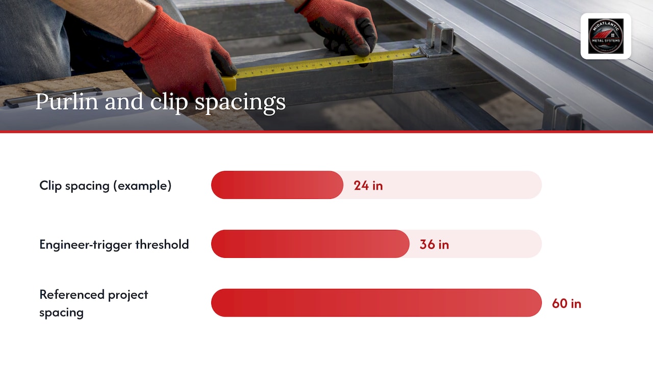
Full-scale testing referenced in industry research shows purlin spacing effects across a wide load range, with 24 gauge panels on 16 gauge purlins holding acceptable spacings from 1 foot to 5 feet depending on wind pressures between negative 97.5 psf and negative 37.5 psf. Higher uplift pushes spacing down; lower uplift and stiffer assemblies allow it to stretch out. The AISI-referenced design example that lands on 5 feet does so with a specific clip spacing and load case attached, not as a standalone recommendation. Treat any number you see in an article, including this one, as a starting point for a table lookup rather than a finished answer.
Primary factors that control allowable purlin spacing
Before you commit to a spacing plan, you need to know what is actually driving the limit. It is rarely one variable. It is usually four or five working together.
- Wind uplift and snow loads, sourced from ASCE 7 for the project location, set the baseline forces the roof assembly has to resist.
- Panel gauge and profile stiffness determine how much unsupported span the cladding itself can carry between purlins without deforming.
- Clip type and clip spacing contribute directly to in-plane stiffness, which changes how much restraint the panel provides to the purlin line.
- Purlin section type and span length set the structural capacity of the framing member itself, independent of the cladding.
- Deflection limits for the cladding cap how much a purlin is allowed to bend under load, since standing seam panels tolerate far less movement than through-fastened systems.
Deflection is the factor contractors underestimate most. A purlin can be strong enough to carry the load and still deflect enough to distort the seam line or trigger oil-canning. Bridging and anti-sag bars address this by tying purlins together laterally, which limits individual member deflection and can let a design use wider spacing than an unbridged line would allow. None of these factors work in isolation. A stiffer panel profile can offset a wider clip spacing. A tighter clip spacing can compensate for a lighter gauge purlin. That interaction is exactly why a single spacing number never applies across projects.
How clip spacing and panel geometry interact with purlin spacing
Clips are not just fasteners. They are the mechanical link that determines how much lateral restraint the panel actually delivers to the purlin, and that restraint is a direct input into allowable spacing.
Fixed clips lock the panel to the purlin at that point, resisting movement in every direction. Sliding clips allow the panel to move longitudinally with thermal expansion while still transferring wind and gravity loads at that location. Clip spacing in documented examples commonly falls between 12 inches and 24 inches on center, and that spacing choice changes the stiffness the assembly provides. Research supported by AISC and AISI found that clip type and panel geometry materially change in-plane stiffness, which means two roofs with identical purlin spacing can behave differently depending entirely on which clip and panel combination sits between the purlin and the weather.
- Fixed clips at tighter spacing generally add more restraint but require careful attention to thermal movement elsewhere in the run.
- Sliding clips preserve expansion capacity but shift more of the stiffness burden onto panel profile and purlin selection.
- Clip spacing changes documented in testing directly altered measured stiffness, confirming that clip choice is not a minor spec detail.
There is no universal number that works across clip and panel combinations. The manufacturer’s load and span table is built around a specific pairing, and swapping either half of that pairing without rechecking the table invalidates the spacing you planned around.
Pro Tip: Confirm clip and panel compatibility with your supplier before finalizing purlin layout, not after the purlins are already installed.
Installation tolerances and alignment: preventing oil-canning and seam problems
Standing seam panels punish sloppy framing in ways through-fastened panels do not. A purlin line that is slightly out of alignment or too flexible under load will telegraph through the finished roof as visible waviness or seam mis-engagement.
- Check purlin straightness against a tolerance in the neighborhood of L/500, a common benchmark referenced in industry technical guidance for cladding that has little tolerance for deflection or misalignment.
- Verify top-flange elevation across the entire purlin line before panels arrive, since even small elevation differences create visible ripples once panels are seamed.
- Confirm cleat orientation and splice locations match the layout the panel supplier used to calculate lengths and clip positions.
- Check bridging positions to confirm anti-sag measures are installed where the design called for them, not just where they were convenient to add.
- Avoid storing materials on unrestrained purlins during construction, since point loads on a purlin line that has not yet been fully braced can introduce permanent deflection before a single panel goes down.
Exceeding these tolerances does not always cause an immediate failure. It shows up months later as oil-canning, seams that do not engage cleanly, or a roofline that looks uneven in low-angle sunlight. Catching alignment problems before panel delivery is far cheaper than catching them after.
Design verification: using manufacturer load/span tables and when to call an engineer
The workflow for verifying purlin spacing is straightforward, even when the inputs are not. Start with the site’s design loads, sourced from ASCE 7 for wind and snow in the project location. Select the panel profile and clip type together, since they function as a single unit. Take those choices to the manufacturer’s load and span table, which will list deflection and strength limits for specific purlin spacing values. Verify that the purlin section you have specified meets or exceeds what the table requires at your target spacing, then document the result for the project file.
A short numeric illustration helps show how the lookup works in practice. Say a project has a purlin line rated for a given uplift pressure, and the design example referenced earlier uses 5 feet of purlin spacing paired with 24 inch clip spacing for that load case. If your project’s wind pressure, panel profile, and clip spacing match that case closely, 5 feet may be defensible. If any one of those inputs changes, the spacing has to be rechecked against a table built for your actual conditions, not borrowed from someone else’s example.
Clip type and panel geometry directly impact allowable purlin spacing and in-plane stiffness, and there is no single-number rule that holds across projects.
Some situations should always trigger a call to a structural engineer rather than a table lookup alone:
- Proposed spacing beyond 36 inches on center for anything other than a pre-engineered, manufacturer-documented assembly.
- High-wind design classifications where uplift pressures push toward the upper end of tested ranges.
- Unusual clip and panel combinations that fall outside the manufacturer’s published table.
- Code-required engineered components, which apply on many commercial and institutional projects regardless of how routine the spacing looks.
Manufacturer tables cover the combinations they tested. When your project sits outside that coverage, an engineer’s review is not optional caution, it is the only way to know the spacing will actually hold.
Contractor’s on-site checklist for confirming purlin spacing before panel delivery
A short pre-delivery check prevents most of the rework that shows up later in a standing seam job.
- Confirm the clip type and clip spacing shown on submittals match what will actually be installed.
- Verify purlin spacing and splice locations line up with the panel layout the supplier used for lengths and clip placement.
- Check top-flange elevation tolerance across the full purlin run before panels are ordered or delivered.
- During installation, verify bridging is in place where specified and measure deflection under construction loads if there is any doubt.
- Confirm clips are installed correctly and that fastener access has not been blocked by trim or insulation.
- After installation, inspect seam engagement lines for consistency and check for visible oil-canning or buckling before calling the job finished.
Running this list before panels arrive, not after, is the difference between a clean install and a callback.
Practical resources and recommended contractor references
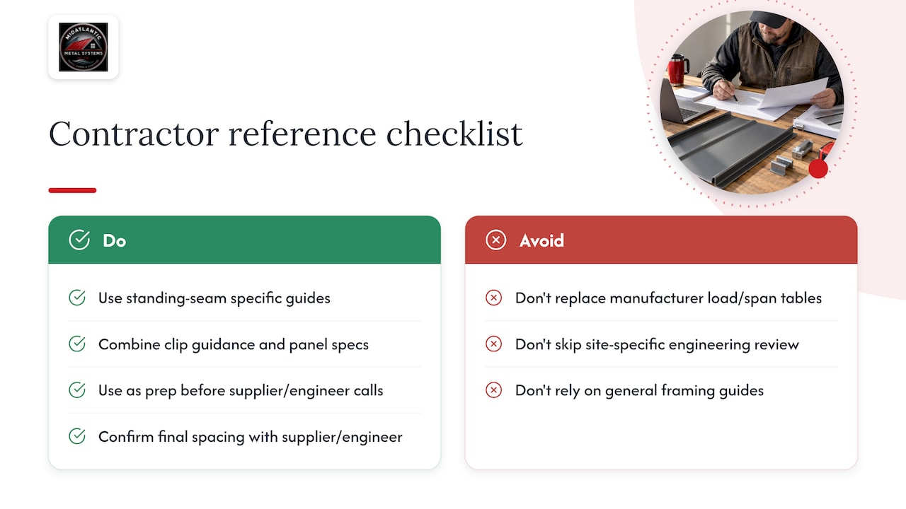
Contractors verifying spacing on an active job benefit from resources built specifically for standing seam systems rather than general framing guides. MidAtlantic Metal Systems’ clip spacing guidance walks through recommended clip spacing for longer panel runs and how that spacing interacts with panel layout decisions. Pairing that resource with the standing seam panel specifications page gives a fuller picture of how panel type affects the spacing you can plan around.
None of these resources replace a manufacturer’s load and span table or a site-specific engineering review. They are reference points for narrowing down questions before you get on the phone with a supplier or an engineer, which is where the final spacing number gets confirmed.
Field perspective: common mistakes and quick mitigations
The most common mistake on standing seam jobs is treating spacing as a single fixed number instead of an output of the load, clip, and panel combination for that specific roof. A close second is skipping clip verification until panels are already on site, which turns a five-minute submittal check into a delivery delay.
Poor purlin alignment causes more callbacks than underspecified spacing does, since a roof can be structurally sound and still look wavy if the framing was never checked for straightness. A mock layout on the ground, temporary bridging during construction, and a short pre-delivery conversation with your panel supplier catch most of these problems before they become expensive.
— Matt Catino
How MidAtlantic Metal Systems can support correct purlin spacing and installation
Once your purlin layout is verified, the next problem is getting panels that actually fit it. MidAtlantic Metal Systems cuts standing seam panels to custom lengths, which means your panel order matches the purlin spacing you confirmed instead of forcing field adjustments to fit stock lengths.
Our 1-inch mechanical lock and 1.5-inch snap lock product lines are manufactured from 24-gauge and 26-gauge Englert steel, and we pair panel orders with coordinated trim and flashing packages so clip and panel compatibility questions get answered before delivery, not during installation. Cut-and-drop delivery services bring custom-length panels straight to the job site, and on-site roll forming options allow fabrication of panels on location when a project’s purlin layout makes stock lengths impractical. If your framing plan needs a technical takeoff to confirm panel lengths against verified purlin spacing, reach out through our contractor supply page and we will work the layout with you before panels are cut.
Sources
- Structural Design Example – Four Span Metal Building Z-Purlin Line Supporting a Standing Seam Roof
- Standing seam system stiffness and clip interaction (AISC/AISI research example)
- Manufacturer/industry technical guidance on standing seam tolerances and oil-canning risks
FAQ
How far should purlins be spaced apart?
Purlin spacing for standing seam roofing typically falls between 12 inches and 60 inches on center, but the correct number for your project comes from the manufacturer’s load and span table for your specific panel, clip, and load combination. Wider spacings near 60 inches only apply in engineered cases with stiffer purlins and matching clip spacing.
Can a standing seam be installed on purlins?
Yes, standing seam panels are commonly installed over purlin framing, and this is a standard assembly method for metal buildings. The purlin spacing, clip type, and panel gauge all have to be selected together and checked against a manufacturer’s table since standing seam systems tolerate less purlin deflection than through-fastened panels.
What is the spacing for 2x4 purlins for metal roofing?
Wood 2x4 purlins are not the framing type addressed in the structural design examples and load and span data used for standing seam metal roofing, which typically reference steel Z-purlins or C-purlins. Spacing for wood framing under metal roofing should be confirmed with the panel manufacturer’s own installation guidance and local building code requirements for the specific application.
How far apart should purlins be for 26 gauge metal roofing?
Spacing for 26 gauge panels depends on the clip spacing and load conditions on the project, not the gauge alone, so there is no single number that applies universally. Testing on 24 gauge panels showed acceptable spacings ranging from 1 foot to 5 feet depending on wind uplift pressure, and 26 gauge panels require the same table lookup against their own manufacturer data before a spacing is finalized.